Marble run · build log
A modular joint, verified geometry, and a physical inventory under review.
A modular marble run printed as single-wall vases: a spiral chute the marble orbits down, a straight drop tube, a catch cup with a belly that keeps bounces inside. Every part nests on the same tapered coupling. This page is the build log, not a shop.
Physical inventory unverified. Historical text on this page reported incompatible print counts, and this tree contains no print log that resolves them. Those counts remain under review.
The coupling numbers below trace to emitted build files, and the marble behavior traces to the embedded simulation log. Neither artifact proves which parts were physically printed or tested.
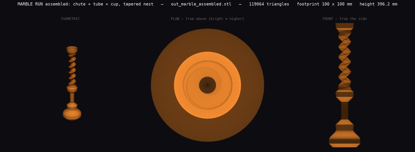
Provenance: source file lost. The image names its own source across the top: out_marble_assembled.stl at 119,064 triangles, drawn by tools/render_stand_stl.py in the public crackle repository. It is a genuine three-view of a real build file, but that assembly is the one render on these pages that cannot be redrawn today: the STL is neither on disk nor anywhere in the repository history, checked 2026-08-04. The parts it shows are still generated individually. Extracted from the page into a file on 2026-08-04.
Why the design predicts a loose joint from a number nobody checked
Historical notes reported a loose joint, but the number of physical chutes and the fit test itself have no resolving print log in this tree. The design diagnosis below is backed by slicer instructions and mesh measurements; it does not verify the physical inventory.
Everything about this coupling is sized around the width of the printed wall, because a single-wall print lays one bead centred on the surface path. The gap between two printed faces is therefore the gap between the two paths, minus one bead. Get the bead wrong and every clearance in the kit is wrong by the same amount.
The kit was designed around a 1.2 mm bead. That figure came from an early estimate and was never once checked against the machine. Reading the instructions the printer actually executed, the bead is 0.95 mm: the slicer was told 1.0 and the flow was set to 95 percent of it. Measuring a second and independent way, by adding up the plastic pushed out over 9,653 real movements, gives the same answer.
With those inputs, the designed gap is three times larger than drawn, and the detent meant to hold the joint falls below its engagement threshold. The constant now carries its measurement and provenance in the code beside it.
Only the socket half of the coupling depends on that number. By geometry, a corrected socket still accepts the earlier spigot design and grips it harder. Whether physical parts were saved by that compatibility remains unverified.
The remaining unknown is the honest one. 0.95 mm is what the machine was told to lay down, and what it really lays is a separate question. So the last word goes to a ladder of test fits, from zero clearance up to fifteen hundredths of a millimetre, to find by hand the tightest one that still comes apart. Those are drawn and checked, and not yet printed.
The joint that failed first, by the numbers
The first coupling was a straight male tube in a straight female tube: surface paths of 55 and 56 millimetres. That leaves 0.5 mm between the two paths. But a vase print lays a wall 1.2 mm wide, centred on the path, so each wall claims 0.6 mm each side of its line. The male's outer face landed about 0.7 mm fatter than the female's inner face. It could not enter. The parts were correct and useless.
The fix is a shallow tapered nest. The male end is a cone from 52 at the tip to 56 at the base. The female mouth opens at 59.2 and narrows to 55.2. The female path stays 1.6 mm outside the male path at every mating height: one full line width plus 0.4 mm of slip. Measured across the emitted meshes, the walls clear by a uniform 0.40 mm through the whole 16 mm engagement, and the taper self-centres. Print drift moves the seating depth a little instead of deciding whether the joint works at all.
What is proven, and what is not
✓ Measured from artifacts
- All three meshes watertight by edge parity, and vase-printable: wall lean measured under 55 degrees.
- Coupling clearance measured cross-part off the emitted files: +0.40 mm through the engagement.
- The chute's rail crest is narrower than the marble, so the marble cannot leave the gutter. Geometry, verified.
- The physical inventory is not verified by any print log in this tree.
○ Not proven yet
- Physical mating and fit-test status are under review.
- Marble dynamics: orbit or hop is decided by a real marble, not a mesh.
- A stretch-fit star ring that crowns each joint. Its geometry is documented; its physical print count and grip test are unverified.
- Long chains, funnel-as-hopper seating, and toddler-grade abuse: untested.
The tension ring
An eight point star sleeve that holds a joint together. Solid PLA barely stretches, but a corrugated ring bends its arms instead of straining its material: the star is the spring. The current version has a two zone bore: the lower half is straight and squeezes the male body 0.9 mm; the upper half rises at the joint's own 5.7 degree cone slope, so it seats flush on the mouth cone inside the rim, and pulling the joint apart drives the cone deeper into the spring and it grips harder. Peak strain stays near one percent at a 3.2 percent stretch.
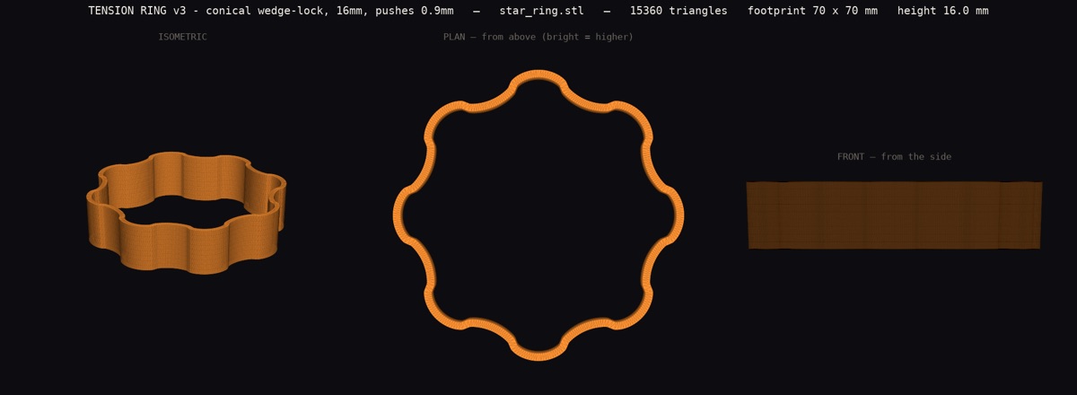
Provenance: recovered 2026-08-04. The image names its own source across the top: star_ring.stl at 15,360 triangles, 70 x 70 x 16 mm, drawn by tools/render_stand_stl.py in the public crackle repository. The copy on disk today is a later and much coarser file parked as star_ring.stl.FAILED, so this image regenerates from the revision in git history (commit 47ee60f, 2026-08-02) rather than from the working copy. Re-rendering that revision reproduces this image, checked pixel against pixel on 2026-08-04. Extracted from the page into a file on 2026-08-04.
The chute was already a sorter and nobody had noticed
Oleg asked for a version with a sorting hole. Going to add one turned up the fact that the hole was already there. The chute wall is a single surface whose radius is one value for each angle and height, which means the narrowest point at every height is the rail crest. Measured off the emitted mesh, band by band down the whole spiral, that narrowest radius is 7.50 mm, dead constant. So a clear 15 mm shaft runs the full height of the tower.
Earlier today this section claimed the rest of that outright: a marble smaller than the crest falls down the middle, a bigger one rides the spiral, so the crest is a sieve. Then the physics engine was pointed at it, and this section briefly said the opposite, that only half of it worked and small marbles stalled in the shaft. That correction was itself wrong, and the mistake is worth more than the result.
The measurement that was really being taken
The test program stopped watching the marble at the exact moment the marble did the interesting thing. The watcher raises a flag the instant a marble goes down the middle, and the test treated that flag as the end of the run, then reported the last depth it had seen. So "stalls partway down" was never a fact about the marble. It was the height at which the stopwatch was switched off.
Watched to the end instead, the small marble falls the whole length of the tower in 0.18 seconds. Dropping freely through that height takes 0.178 seconds, so it touched nothing at all on the way down. Two different measurements, agreeing.
What the crest actually does
So it is a sorter, and what decides the outcome is where the marble is fed, not just how big it is. Dropped down the middle, the crest tells the two sizes apart cleanly and they separate in both time and place: one out the bottom in a fifth of a second, the other spiralling out four times later at the rim.
The obvious next sentence was that a funnel on top delivers exactly that. It does not, and this is the third thing this section has had to take back today. Asking how accurate the aim has to be gives a brutal answer:
The tolerance is about a millimetre, which is simply the gap between the marble and the shaft it has to thread. The pour funnel that exists has a 55 mm spout, so it scatters marbles across the whole opening and sorts nothing. Aim that good needs a guide tube barely wider than the marble, and no such part has been made.
Which points at a better design than the one being defended here. A tube sized between the two marble sizes is itself the sieve: the small one enters and is delivered centred by the tube, the large one cannot enter at all, and the sorting happens at the top where you can see it instead of asking a helical crest to catch a millimetre of aim.
So that was modeled, and it is half right in simulation
A sort head: a catch bowl above a guide tube two marble-diameters long, above a standard coupling. On its own it behaves perfectly in simulation. Poured anywhere in the bowl, right out to the rim, every small marble goes through and every large one is held.
Combined with the chute in simulation, one half holds and the other does not:
The reason is worth more than the part. A guide tube removes error in where the marble is, but not in which way it is moving. A marble that enters the tube at an angle leaves it still travelling sideways, and just below the tube the piece widens out to the coupling, where nothing guides anything. That short unguided stretch is enough to carry it off the shaft. Testing the head by itself hid this entirely, because the head's own exit is close to centred; the damage happens in the part underneath.
Two candidate fixes, neither built: a longer tube to bleed off the sideways motion, or a straight drop below the tube instead of an immediate flare. Both can be tested in the simulation before anything is printed, which is the point of having it.
A marble already travelling in the gutter, by contrast, rides no matter what size it is. The same wall-of-death effect that makes the chute work presses it outward with solid flank underneath it the whole way round, so it never reaches the middle. That part of the earlier correction stands, and it is a real constraint on how a sorting tower has to be fed.
Three claims were published here today about this one crest, and two were wrong. Both wrong ones came from the measuring apparatus rather than the part: first a clear vertical column assumed to be a reachable one, then a stopwatch stopped early. The geometry has been telling the truth throughout.
The tolerance work still stands: a printed hole comes out about a quarter of a millimetre under the model, so the generator refuses any pair of marble sizes closer than 0.95 mm, and refuses a hand-picked crest that would drop the marble meant to ride. And the first thing to print is still a gauge, because none of this can be aimed until the marbles are measured.
Leaning the tower, and what the lean costs
A chute can now tilt off vertical while both of its coupling ends stay upright and round, so a leaning segment still joins any other part and the stack simply steps sideways. That works because tilting a shape by shearing it sideways slides each horizontal slice without distorting it, and a circle slid sideways is still a circle.
The limit is the printer, not the geometry. These parts are printed as a single continuous wall, and a wall leaning more than about 55 degrees off vertical will not hold itself up. The spiral already spends 51 of those degrees. The first estimate here was that only 4 degrees were left, and that estimate was wrong: tilting the part rotates the surface, and the steepest face is not the one facing the tilt, so the wall only gains about a quarter of a degree per degree of lean. Measuring instead of assuming, and pushing until it actually failed rather than stopping at a number that passed:
Past the ceiling the part is renamed to a failed file rather than saved, with the measured wall angle and the setting that buys more room.
The base, and why a wide plate cannot work
The obvious base for a tower is a big flat plate. The arithmetic says no, before any plastic is spent. A chute weighs 46.9 grams, measured from the surface area of the file itself. Tip a tower and the thing holding it down is its own weight acting across the base; the thing pushing it over is a sideways knock acting at its height. Work that through and a knock of one newton, which is about a hundred grams of hand, needs a base half a metre across.
Worse, that answer does not improve with a shorter tower. Mass grows with height at the same rate the leverage does, so the required plate is the same half metre whatever you build. There is no plate that works.
What works is weight down low, so the base is a tray you pour dry sand into. About 550 grams of sand brings that same one newton knock down to a base 186 mm across, which prints. The generator solves the footprint and the amount of sand together, because they fight each other: more sand means a smaller base, which means a smaller tray, which means the same sand sits deeper. Bases exist for one, two and three segment towers, single and double socket. The triple socket version is refused: it needs 361 mm and the bed is 340. Nothing here is printed yet.
From a stack to a structure
A tower is a stack of chutes. Three more pieces turn stacks into something you can build with, and each one is here because arithmetic said the obvious version would not work.
Bases hold sand, not width
Covered above: a knock needs half a metre of plate, and that answer does not improve with a shorter tower, because mass grows with height as fast as the leverage does. So the base is a tray you pour dry sand into. Five sizes exist, one to four segments, one or two towers. The three tower version refuses itself: it needs 361 mm and the bed is 340.
One correction worth keeping visible. The chute's weight was recorded as 46.9 grams, and that figure had been calculated with a wall thickness the machine stopped using. Re-measured off the file itself it is 37.0 grams, so the constant was 26 percent heavy. Nothing broke, because an over-heavy tower asks for a wider base, and a wrong number that makes things safer is the kind nobody ever finds.
The brace threads on, and the window is narrow
Two ballasted towers tied together are far stiffer than two standing alone. The tie is a flat plate that threads onto a segment's coupling before that segment drops into the one below, then rests on the rim, so it needs no clip.
That only works if the hole is wider than the part passing through it and narrower than the rim it sits on. Measured, that window is 2.90 mm across against the 1.80 mm the fit needs. Below that number a clip would have been the only honest answer.
Its stiffness check was wrong when first written: it used the whole plate's width as the beam, when the only material bridging the two rings is a 25 mm bar. It overstated stiffness by two and a half times and was passing plates the design's own physics rejects. Corrected, the shipped thickness has 21 percent of margin rather than the 70 it claimed.
The trough, and a measurement that was wrong three times
The last piece runs a marble sideways and downhill from one tower into a shorter neighbour, so a run cascades across a base instead of ending at the floor. The slope is not chosen: the run has to fall by one full coupling depth across one tower spacing, so the receiving socket sits below the delivering exit, and that fixes it at about 17 degrees. The outer wall is taller than the inner one, because a ball going round a curve is thrown outward.
The interesting part is the check, which was wrong three times, and every failure was in the measuring rather than the part:
Then the check could not be made to fail, because the channel is sized from the marble, so asking for a bigger ball simply widens the groove. A check that cannot fail is decoration, so the generator gained a way to pin the channel independently. A 16 mm marble in a channel pinned narrow now fails at 14 mm and the file is quarantined rather than saved.
None of these three has been printed.
Run it yourself, and read the test
The chute is not only drawn, it is simulated. The physics engine below runs the published geometry, and the same code is the QA gate: what you poke here is the test the part passed. It answered the kit's oldest open question. The marble orbits, it does not hop.
And the gate run, verbatim, numbers included. It is the log the check actually printed, not a retelling of it:
Honest reading: this is a model until the physical marble agrees with it. The physical inventory and real-run status are unverified. When physical evidence and simulation disagree, the simulation gets fixed and the correction stays on this page.
Reproduce it
Everything is generated by small dependency-free Python scripts in the public crackle repository. No CAD, no downloads beyond the repo. Each script emits a binary STL and verifies itself; a separate gate re-measures every claim. Run any of them with python3, nothing to install.
spiral_chute_stl.py · the hero: helical gutter, captive marble, vase mode
drop_tube_stl.py · straight fall, same coupling both ends
catch_cup_stl.py · terminus bowl, belly keeps bounces in
star_ring_stl.py · stretch-fit star crown for the joints; physical count unverified
marble_gauge_stl.py · print this one first. Graded rings, 12 to 20 mm: drop a marble through and find out what you actually own
base_ballast_stl.py · the sand tray base, footprint and ballast solved together
brace_stl.py · the tie that threads onto a coupling and rests on the rim
transfer_stl.py · the trough from one tower to the next, slope derived not chosen
transit.py · can a rigid part actually be threaded through a bore. Proof, not a margin
qa_stl.py · the gate: watertight, printable, bed fit. It fails loudly or it passes.